

Access a device graphic
You can reach a device graphic from two locations:- Device details page — select a device from the devices list, open its details, and click the
Graphictab - Graphics module — click
Graphicsin the left sidebar, select theDevicestab, and open an existing device graphic
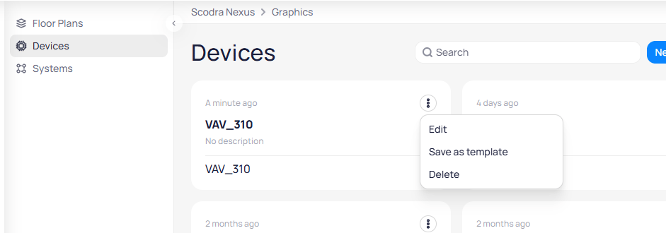
The Graphics module Devices tab lists device graphics with options to edit, save as template, or delete
Edit, Save as template, or Delete options.
Create a device graphic
You can create a device graphic from two entry points:- Device details page — navigate to a device, click the
Graphictab, and click+ Create New - Graphics module — click
Graphicsin the left sidebar, select theDevicestab, and clickNew Graphic
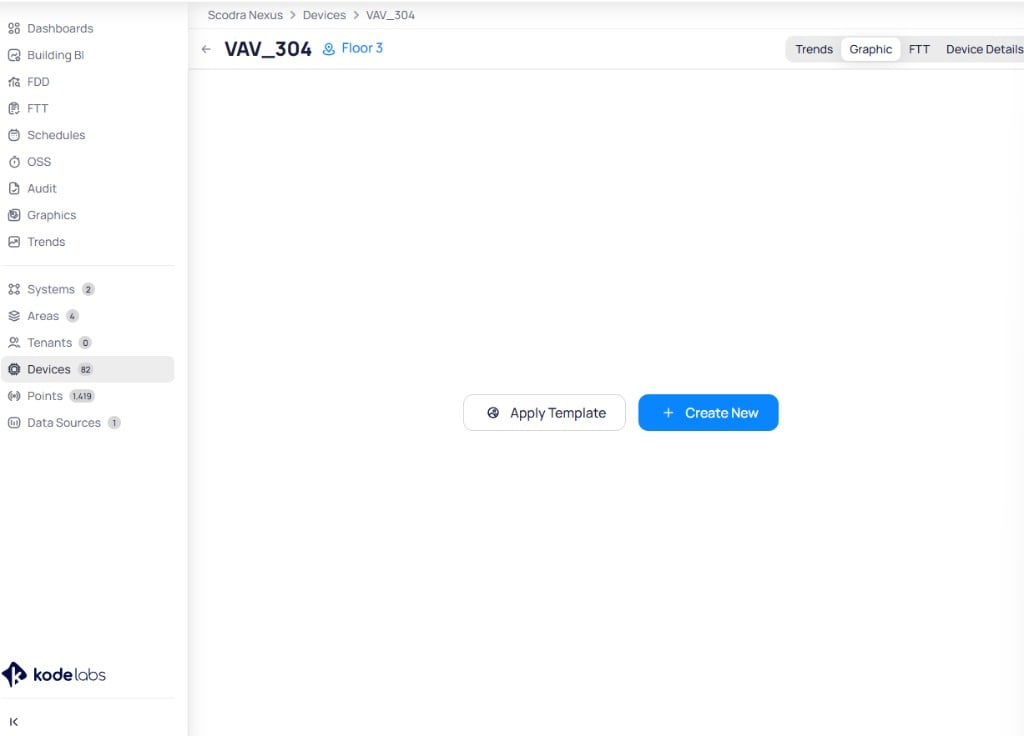
The Graphic tab on a device shows options to apply a template or create a new graphic
+ Create New to open the New Device Graphic dialog.
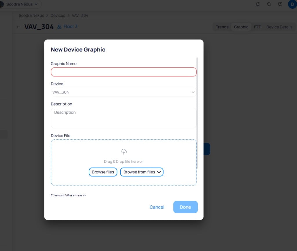
The New Device Graphic dialog collects the graphic name, device assignment, description, and an optional device file upload
Browse files to upload from your computer, or click Browse from files to select from previously uploaded files.Done to create the graphic and open it in the Graphic Tool editor.
Build the device graphic
The Graphic Tool editor provides three tabs for building device graphics: Devices, Elements, and Basics.Devices tab
TheDevices tab lists all devices and their points. The main device assigned to this graphic appears at the top of the list with a red flag icon. A green checkmark with a number indicates how many points from that device are already placed on the graphic.
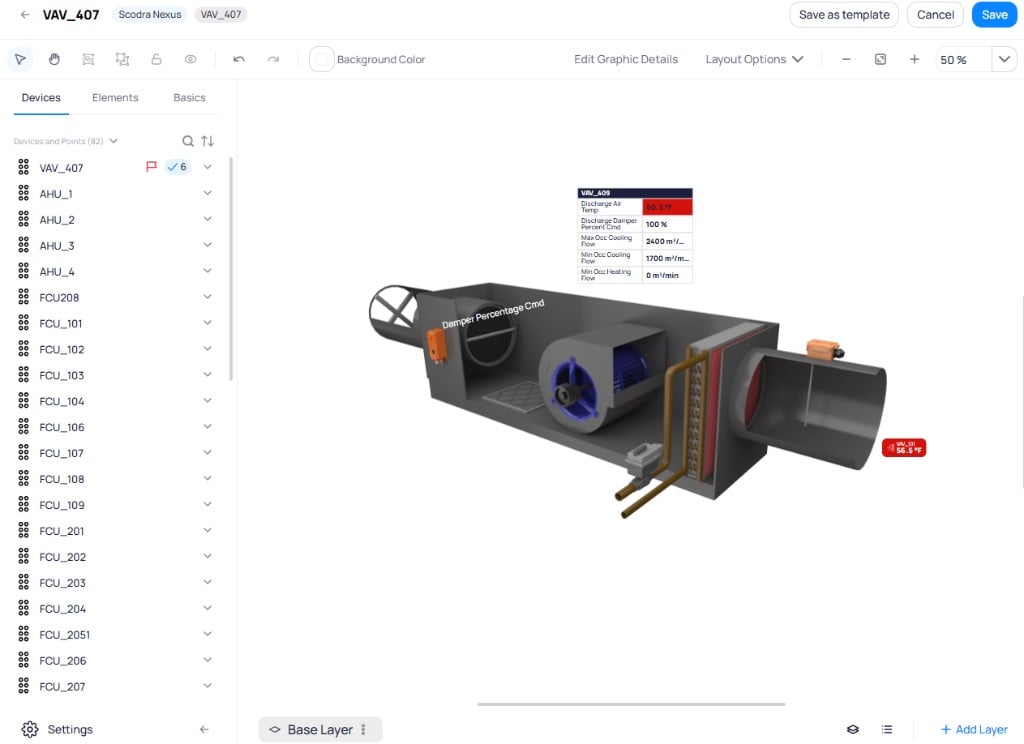
The Devices tab shows the main device with a red flag and all available devices with their points
Elements tab
TheElements tab lists all elements placed on the graphic canvas, including device markers and text labels. Select an element from the list to highlight it on the canvas and access its style options.
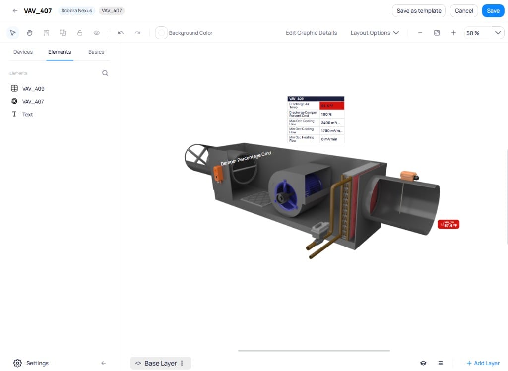
The Elements tab lists placed elements such as device markers and text labels
Basics tab
TheBasics tab contains shapes, device widgets, uploads, and built-in drawings for constructing device graphics.
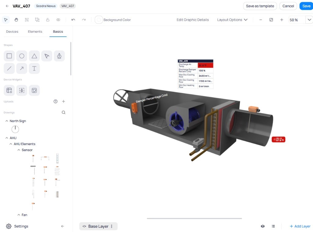
The Basics tab provides shapes, device widgets, uploads, and built-in drawing components
- Shapes — add rectangles, circles, triangles, arrows, polygons, lines, and text labels
- Device Widgets — add device tables, zone tools, and pivot tables
- Uploads — upload custom images from your computer
- Drawings — use pre-built equipment components (AHU elements, sensors, fans, coils) from the built-in library
Save as template
Device graphics can be saved as templates and applied to other devices of the same type. ClickSave as template in the upper right corner of the editor.
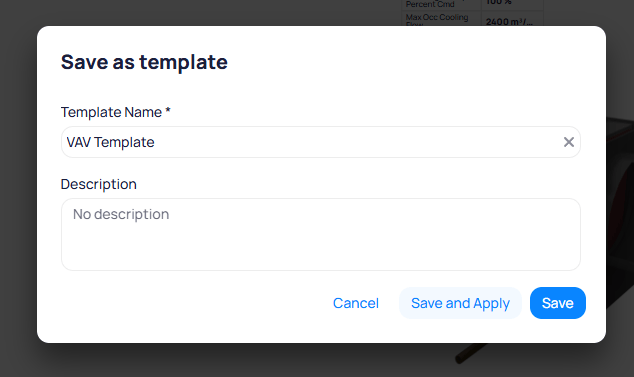
The Save as template dialog lets you name and describe the template
VAV Template).- Save — saves the template for future use
- Save and Apply — saves the template and opens the Apply Template dialog, where you can select other devices to apply the template to
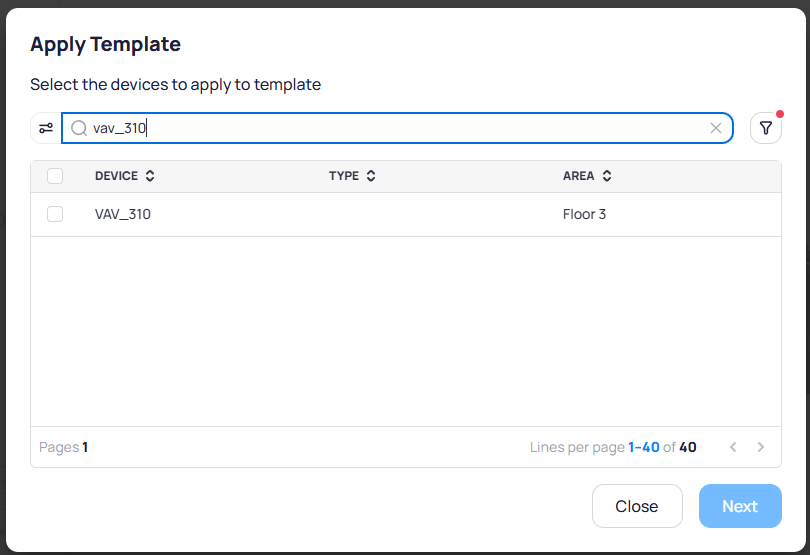
The Apply Template dialog lets you search and select devices to apply the template to
Next to proceed.
On the next step, choose how the template maps points to the target devices:
- Ontology field — matches points based on their ontology classification
- Point name — matches points based on their exact point names
Compatibility column shows how many points from the template match the target device (for example, 6/6 means all six points matched).
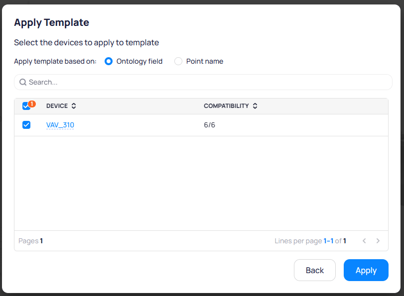
Apply template based on Ontology field matching, showing compatibility score per device
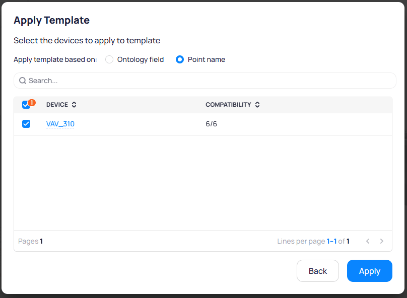
Apply template based on Point name matching
Apply. The Activity Log tracks the template application status.
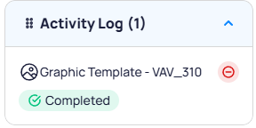
The Activity Log confirms the template was applied successfully
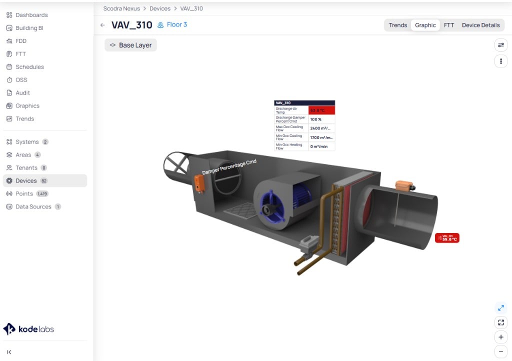
The device graphic on VAV_310 after applying the VAV Template
Graphic tab by clicking Apply Template.
Manage device templates
ClickTemplates at the bottom of the Graphics module sidebar to view all saved device templates.
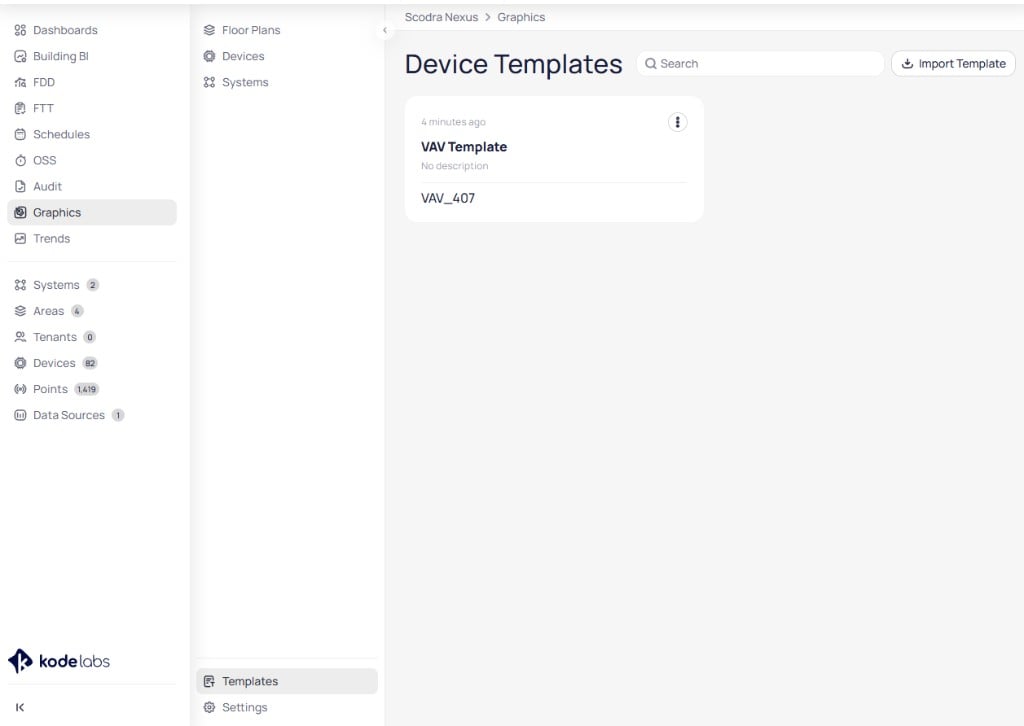
The Templates page in the Graphics module shows saved device templates with search and import options
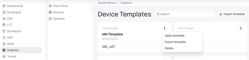
The three-dot menu on a template card provides Apply template, Export template, and Delete options
Apply a template
SelectApply template to open the Apply Template dialog. Search and select the devices you want to apply the template to, then click Next.
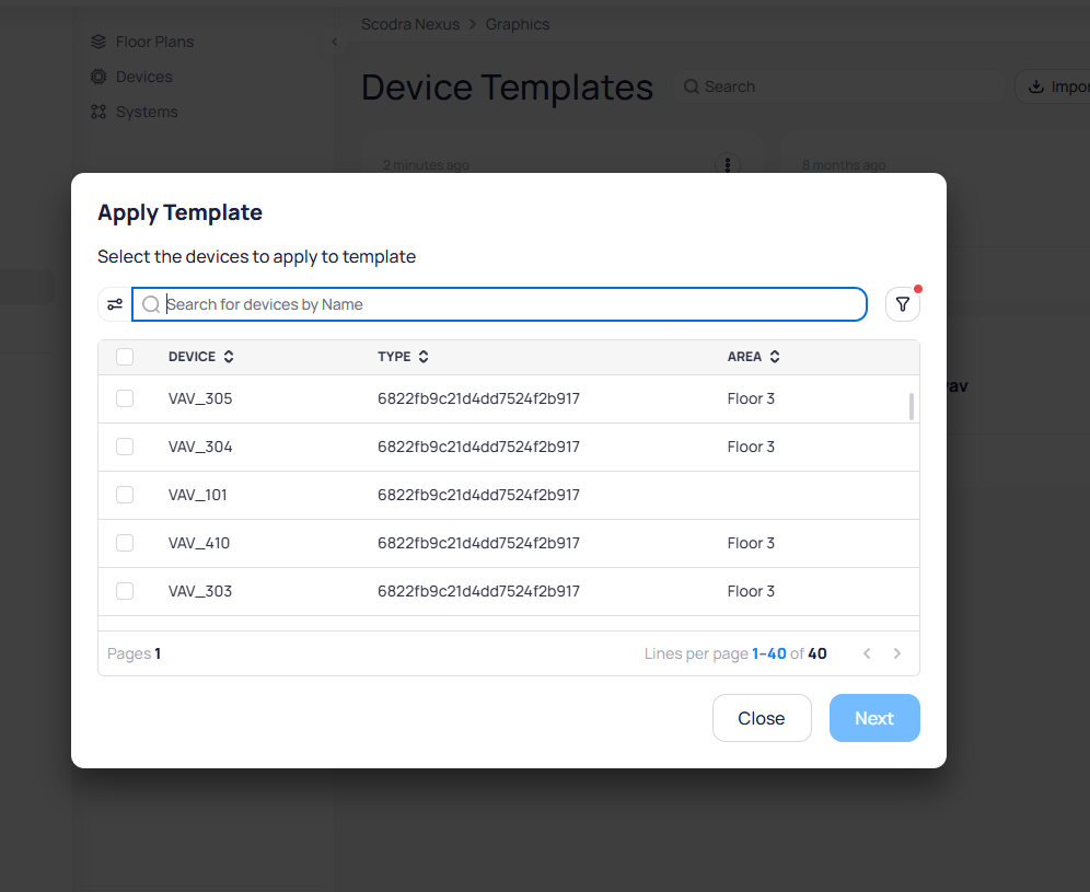
Select devices to apply the template to from the searchable device list
Apply.
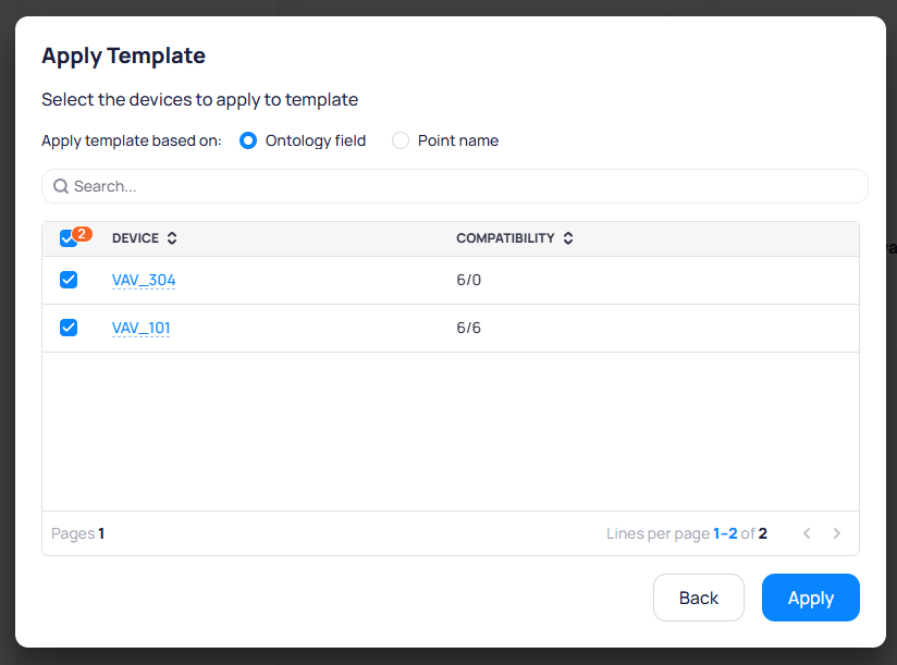
Review compatibility scores before applying the template to selected devices
Export and import templates
SelectExport template from the three-dot menu to generate a shareable link. The link is copied to your clipboard automatically.
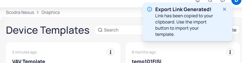
A notification confirms the export link has been generated and copied to the clipboard
Import Template at the top right of the Device Templates page. Paste the exported link, enter a name and canonical type, and add an optional description.
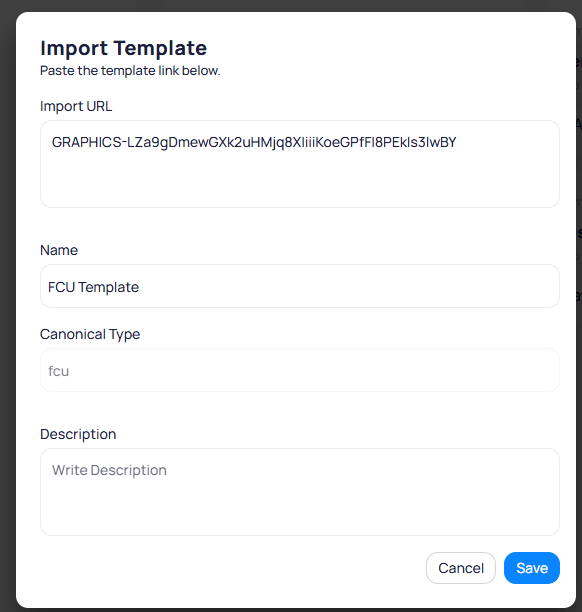
The Import Template dialog accepts the exported link, a template name, canonical type, and description
FCU Template).fcu). This value is carried over from the exported template and cannot be edited.Save to add the template to your Device Templates library.
Interact with writable points
Writable points on a device graphic display an interactive indicator. Click a writable point marker to open the command panel. The panel displays the device’s variables on the left and the action form on the right.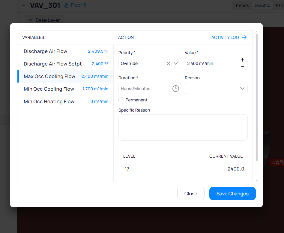
The command panel shows device variables and the action form for overriding a point value
- Priority — select the command priority level (for example,
Override) - Value — set the target value. Use
+and-to adjust. - Duration — specify how long the command remains active. Check
Permanentfor an indefinite override. - Reason — select a predefined reason from the dropdown
- Specific Reason — enter a custom reason for the change
Save Changes to send the command, or Close to cancel. Click Activity Log in the upper right corner to view the command history.
Command actions and priority levels
Cloud BMS uses a BACnet-inspired priority model for writable points. The same command dialog appears for BACnet and non-BACnet integrations, such as REST API thermostats. How each action maps on the device depends on the connector.BACnet points that accept commands have 16 priority levels (1 is highest, 16 is lowest). When every level is empty (null), the point uses a fallback / default value (Relinquish_Default in BACnet). That fallback is not a 17th BACnet priority. Some interfaces label it as level 17 for display only.Override and Set turn different knobs under the hood, even when the visible value looks the same.Override, Auto, and Set borrow Niagara-style action names. Release is a Cloud BMS action that clears a Set.In Niagara-style control, Set keeps a non-null fallback so sequences and logic keep a reliable baseline. Use the priority array (including Override) for programmed automation and temporary exceptions.To make Set write to priority 16 instead of the fallback or default, enable Set in Slot16 (Niagara) on the point. Configure that option from device details, device templates, or points batch update.Tables on device graphics
Add table views to a device graphic to display multiple point values in a structured format. Tables are useful when a device has many points that do not map well to specific positions on a diagram.- Select points from the device (or from related devices)
- Tables support two columns: point name and current value
- Customize colors, column width, and font sizes
- Batch-edit table styling across the graphic
Use device graphics for troubleshooting
Device graphics support troubleshooting by providing a visual context for equipment behavior:- Ductwork and airflow visualization — position supply air, return air, mixed air, and exhaust temperature readings along the airflow path to trace issues through the system
- Valve and damper positions — display valve and damper positions alongside their corresponding temperature or pressure readings to identify control loop problems
- Alarm and fault indicators — point status icons (alarm, down, fault, stale, overridden) appear next to markers, highlighting which points have active issues
- Setpoint comparison — use difference-from-setpoint smart markers to visually identify when a device is not achieving its target