

Area hierarchy
Areas follow a top-down structure:- Site is the top level, representing the entire building
- Floor divides the building into vertical levels
- Zone/Room subdivides floors into specific spaces
Access areas
ClickAreas in the left sidebar menu from your building view. Select a floor from the area list on the left to display its floor plan with device overlays and live data.
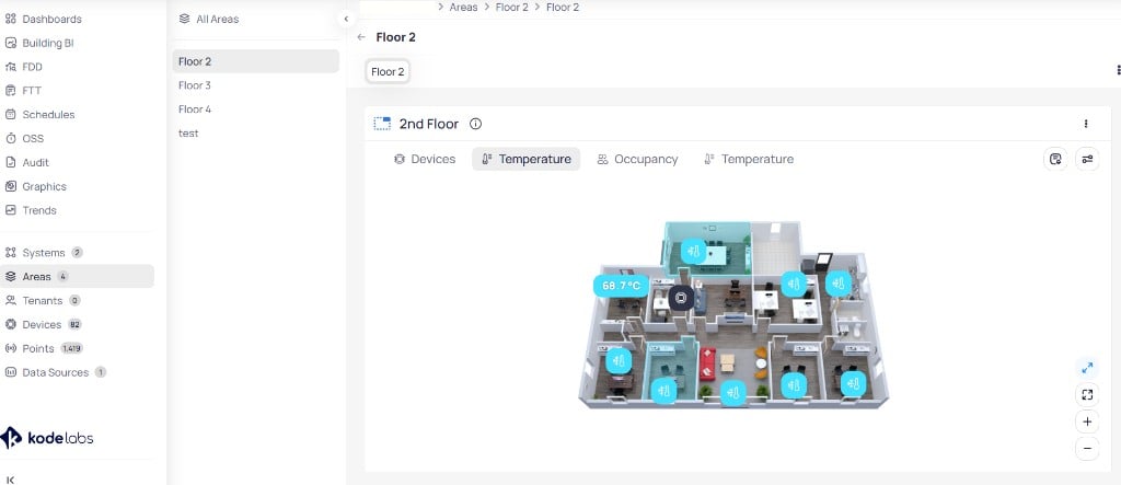
The area view shows the floor list on the left, layer tabs for device categories, and the floor plan with live device markers
Floor plan navigation
The floor plan widget displays devices on a spatial layout. Use the layer tabs (Devices, Temperature, Occupancy, and others) to switch between device categories.
Use the following controls to navigate the floor plan:
- Pan by holding the left mouse button and dragging
- Zoom using the
+and-buttons in the lower right corner - Reset view by clicking the four outward arrows icon
- Smart Markers toggle to enable or disable smart marker display
- Legend toggle to show or hide the icon legend with value ranges
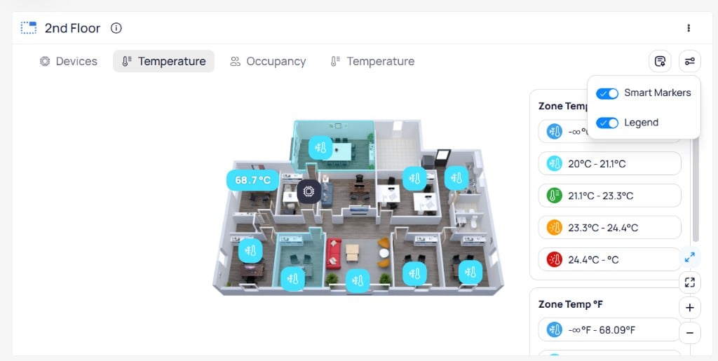
The Smart Markers and Legend toggles control marker display and the legend panel shows the configured value ranges
Interact with devices on the floor plan
Hover over a device marker on the floor plan to expand its point values. Writable points display an edit icon next to the value.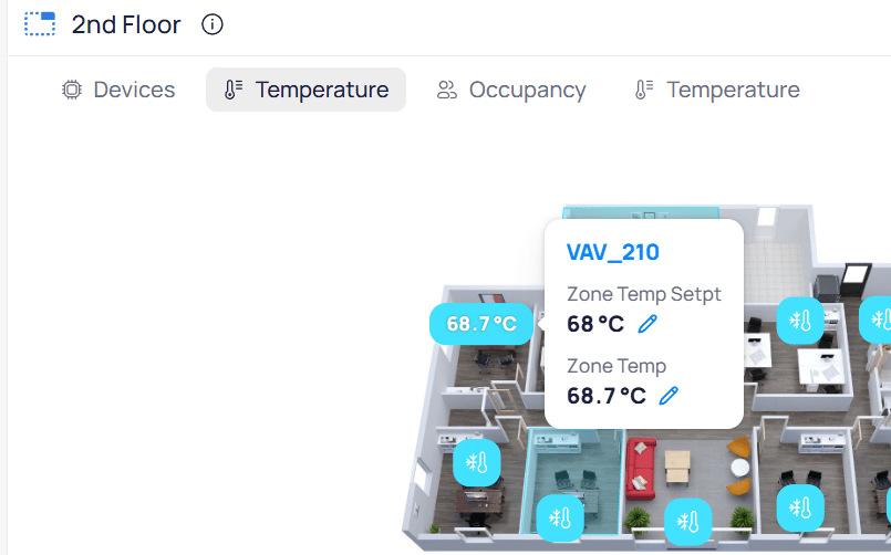
Clicking a device marker reveals its point values with edit icons for writable points
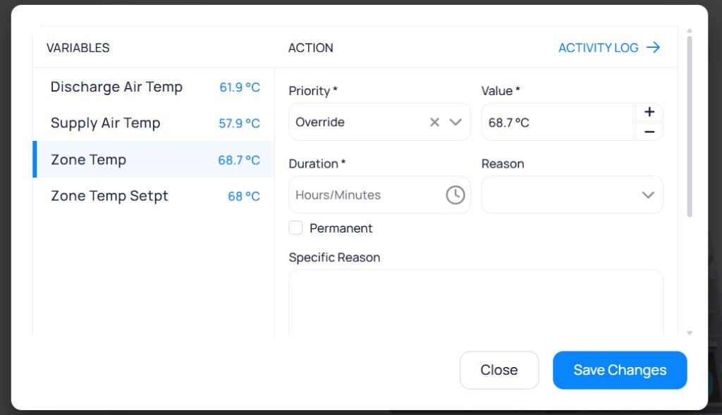
The command panel lets you override a point value with a specified priority, duration, and reason
- Priority — select the command priority level (for example,
Override) - Value — set the target value. Use
+and-to adjust. - Duration — specify how long the command remains active. Check
Permanentfor an indefinite override. - Reason — select a predefined reason from the dropdown
- Specific Reason — enter a custom reason for the change
- Click
Save Changesto send the command, orCloseto cancel
Activity Log in the upper right corner of the panel to view the command history for the selected point.
Command actions and priority levels
Cloud BMS uses a BACnet-inspired priority model for writable points. The same command dialog appears for BACnet and non-BACnet integrations, such as REST API thermostats. How each action maps on the device depends on the connector.BACnet points that accept commands have 16 priority levels (1 is highest, 16 is lowest). When every level is empty (null), the point uses a fallback / default value (Relinquish_Default in BACnet). That fallback is not a 17th BACnet priority. Some interfaces label it as level 17 for display only.Override and Set turn different knobs under the hood, even when the visible value looks the same.Override, Auto, and Set borrow Niagara-style action names. Release is a Cloud BMS action that clears a Set.In Niagara-style control, Set keeps a non-null fallback so sequences and logic keep a reliable baseline. Use the priority array (including Override) for programmed automation and temporary exceptions.To make Set write to priority 16 instead of the fallback or default, enable Set in Slot16 (Niagara) on the point. Configure that option from device details, device templates, or points batch update.Area events
Select the active events icon on the floor plan to view fault detection events specific to that area. This filtered view shows only the events related to devices in the selected floor or zone.Add a dashboard to an area
When you select an area that has no dashboard configured, the view displays a “No Dashboard Added Yet” message with an option to create one.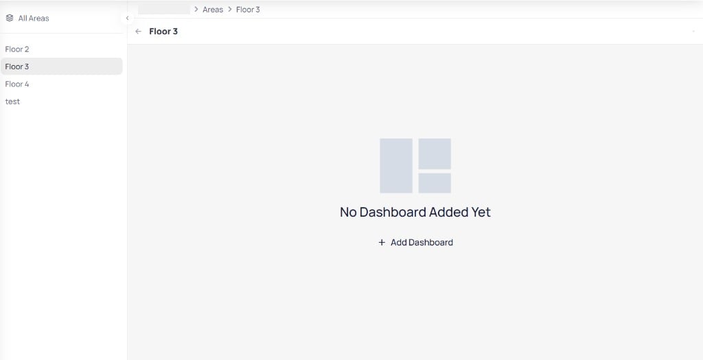
An area without a dashboard displays a prompt to add one
+ Add Dashboard to open the creation dialog.
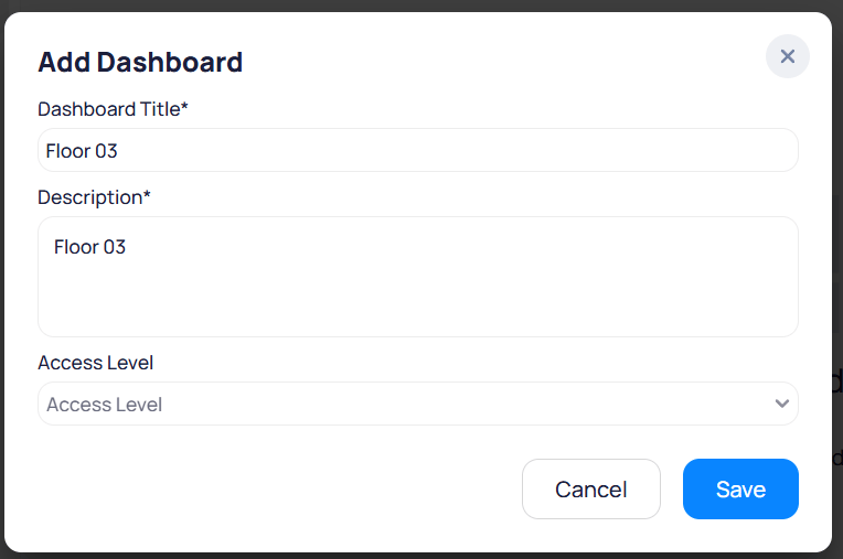
The Add Dashboard dialog collects a title, description, and access level
Floor 03).Add a BIM model to an area
Cloud BMS supports 3D BIM models on area dashboards. Add a BIM file in building settings first, then add a BIM Model widget to the area and place device points on the 3D floor plan.Add the BIM Model widget
Open the area dashboard menu
Areas and select an area (for example, Floor 06). On the area dashboard, select the three-dot menu in the upper-right corner and choose Add Widgets.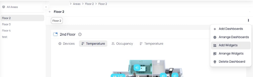
The dashboard menu includes Add Widgets for adding a BIM Model or other widget types
Select BIM Model
BIM Model and click Add.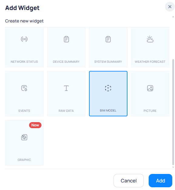
The Add Widget dialog lists BIM Model among available widget types
Enter card details
Next.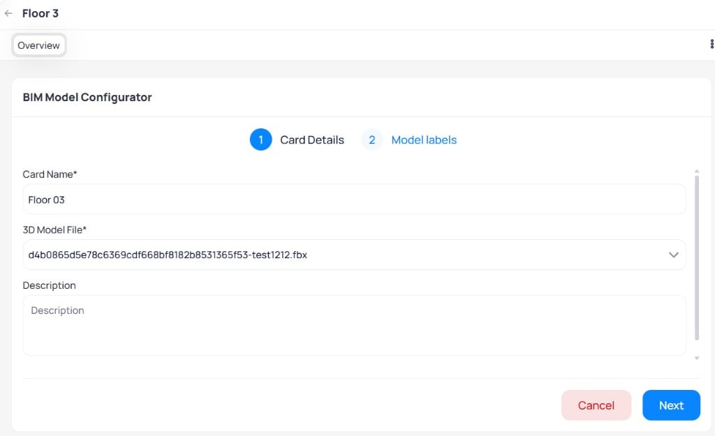
Card Details step where you name the widget and select the uploaded 3D model file
Place device points on the model
Save when placement is complete.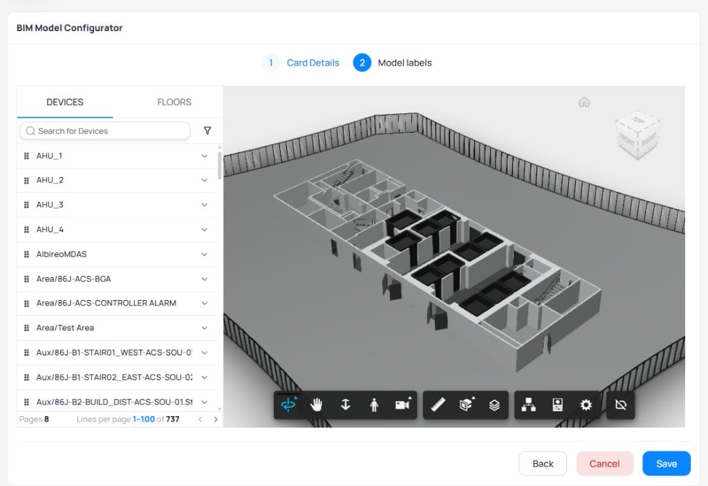
Model labels step with a device list and interactive 3D viewer for placing points on the floor plan
View the 3D floor plan
After you save the widget, the area dashboard shows an Overview tab and a 3D Floor Plan tab. Open 3D Floor Plan to view the BIM model with placed device markers and layer controls. The BIM widget displays the configured card name, the 3D model, and device point markers you placed during setup.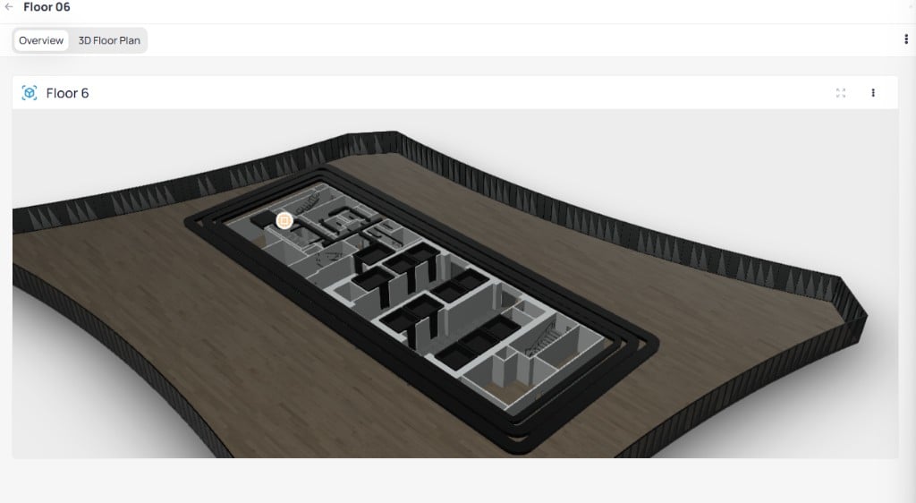
BIM Model widget on the area dashboard showing the 3D floor plan and device markers
Add a graphic widget to an area
You can add a graphic widget to an area dashboard to embed a floor plan graphic directly on the area page.Open the dashboard menu
Add Widgets.The dashboard menu provides options to add and arrange dashboards and widgets
Select the Graphic widget
Graphic and click Add.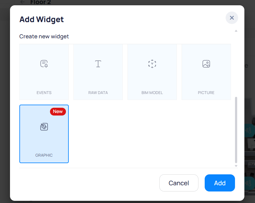
The Add Widget dialog offers widget types including Events, Raw Data, BIM Model, Picture, and Graphic
Choose or create a graphic
Create new graphic to build one from scratch. Click Next to add it to the dashboard.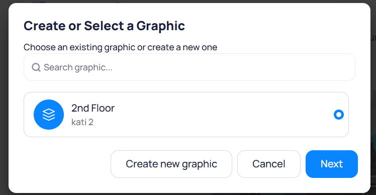
Select an existing graphic or create a new one to embed in the area dashboard
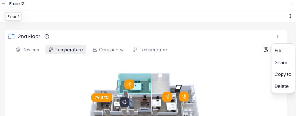
The area dashboard shows a floor plan graphic with layer tabs and a menu for editing, sharing, copying, or deleting the widget
- Edit — open the graphic in the Graphic Tool to modify markers, layers, or overlays
- Share — generate a shareable link to the dashboard
- Copy to — copy the widget to another area’s dashboard
- Delete — remove the widget from the dashboard
Manage areas
ClickAreas in the left sidebar to view the areas list. The list shows each area’s name and device count.
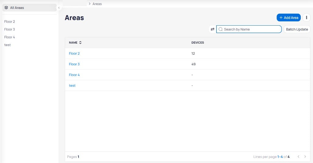
The Areas list displays all areas with their device counts, search, and batch update options
Add areas
Click+ Add Area to open the Add Areas dialog. Enter a name for each area. Click + Add Row to add additional areas, or click Add Multiple Rows to add several at once.
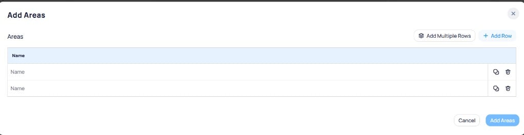
The Add Areas dialog lets you create one or more areas by entering names in each row
Edit and delete individual areas
Hover over an area row and click the three-dot menu to accessEdit or Delete for that area.

The row menu provides Edit and Delete options for individual areas
Delete areas in bulk
ClickBatch Update to enter selection mode. Select the areas you want to remove, then click Delete Area(s) in the lower right corner.
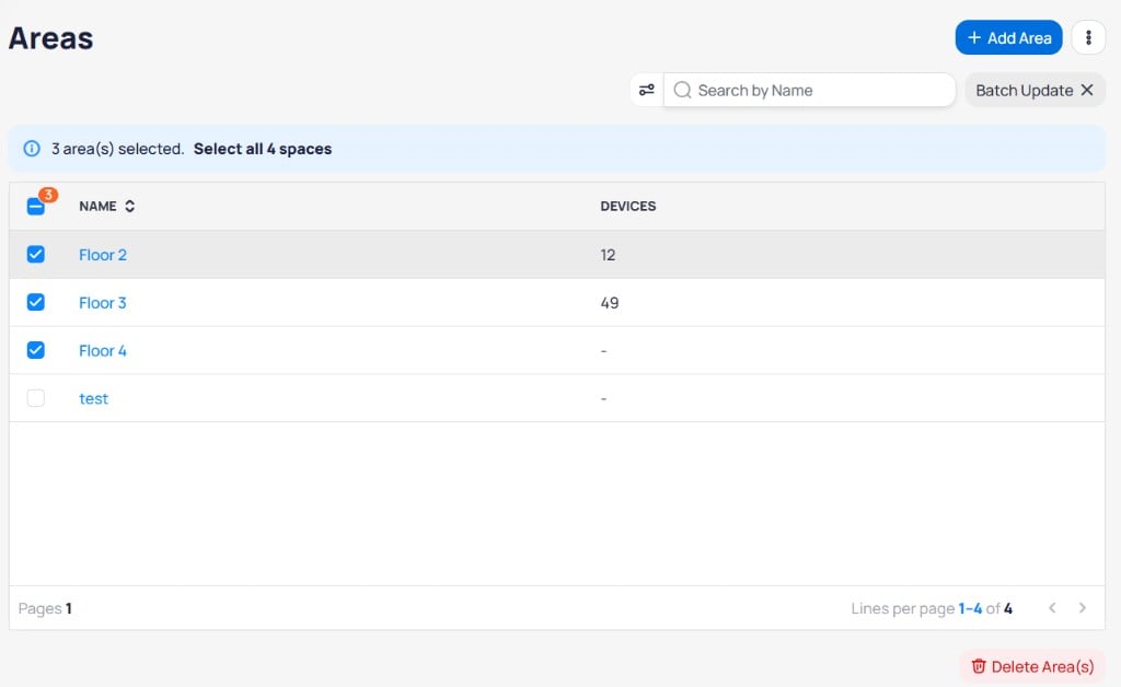
Batch Update mode lets you select multiple areas for bulk deletion
Reorder areas
Click the three-dot menu next to+ Add Area and select Reorder Areas. Drag and drop the areas into the desired order, then click Save.
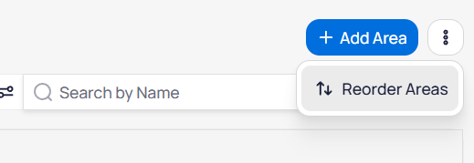
The Reorder Areas option is accessible from the three-dot menu next to the Add Area button
Assign devices to areas
Devices are assigned to areas during initial discovery or through the device details page. To reassign a device to a different area:- Open the device’s details page and edit the
Areafield - Use the device batch update feature to reassign multiple devices at once