

When to build a custom workflow
Use the library when a standard VAV, FCU, AHU, or heat pump workflow already matches the component you need to score. Build a custom workflow when you need a different command path, sensor set, or success criteria. Common situations that lead to custom work:- Continuous commissioning at scale for terminal units across heating and cooling seasons
- Retail or multi-site validation before and after a service visit
- New construction prioritization so agents re-test failed units instead of spot-checking a small sample
Workflow architecture
Every workflow in the KODE standard architecture contains the following components:Time control parameters
KODE standard architecture uses three time control parameters in every workflow. These are user-adjustable and applied consistently to each sequence.Sequence architecture
Sequences are the core building blocks of a workflow. Each sequence tests one mechanical component by issuing a command, monitoring the sensor response, and scoring the result. Sequences are isolated to the smallest individual component of the device that you want to test and score.Components of a sequence
Sequence string builders
Each sequence generates six messages in the test report: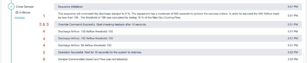
A test result showing the six output messages generated per sequence, numbered 1 through 6
Step 1: conceptual design
Define each sequence, write command, and success criteria before opening the logic builder. This section uses VAV Damper Operation as a working example.Define pre-condition checks
Define each sequence
Classify all inputs
Step 2: build the workflow
Set up the main folder
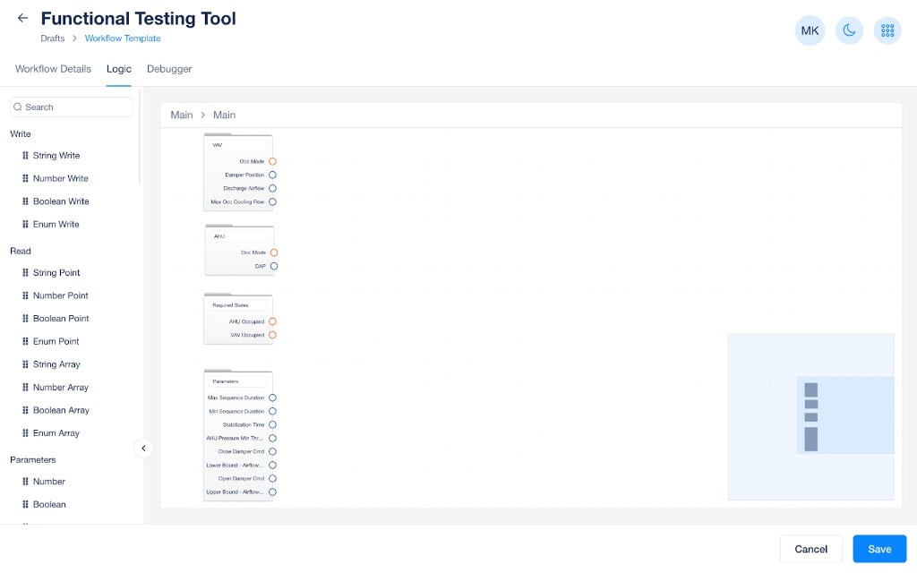
Step 1: Main folder populated with VAV, AHU, Required States, and Parameters sub-folders
Build the high-level structure
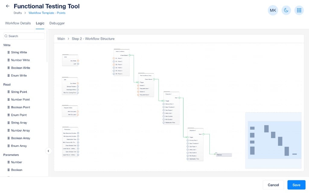
Step 2: High-level workflow structure with initial conditions, pre-condition check, and sequence folders
Connect points to folders
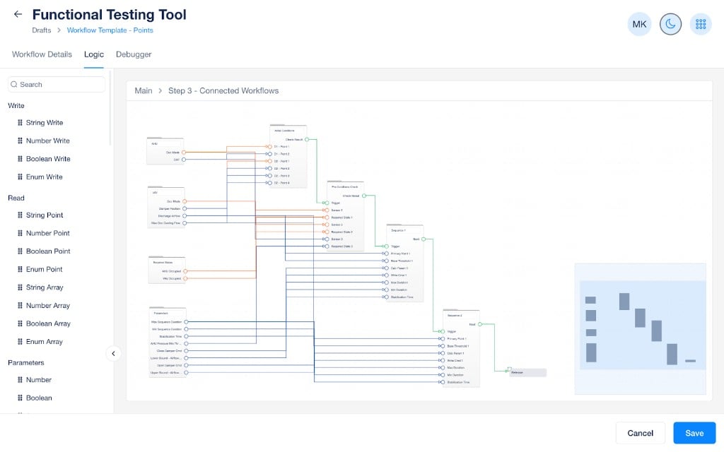
Step 3: All points connected from the main folder into the workflow structure
Build each sequence
- Am I writing the correct point field?
- Am I doing the proper calculation on my base threshold (multiplication, addition, subtraction)?
- Am I doing the proper comparison (less than, greater than, equal to)?
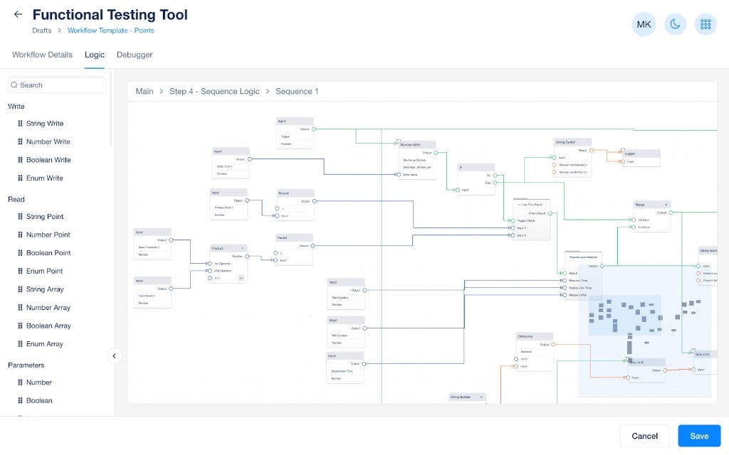
Step 4: Inside Sequence 1 showing the complete logic with write command, threshold calculation, comparison, timing, and string builders
Step 3: build text output
Use string builder blocks to combine static text with variable inputs from the logic. The command success/failure, minimum duration, and stabilization messages are standard and generally do not require modification. Focus on customizing the three messages below.Backtick text represents dynamic values populated by drawing lines from logic blocks into the string builder.Sequence description message
This message describes the command being issued, the maximum time duration, the success criteria, and how the thresholds were calculated. Template:- This sequence will command the VAV Damper Cmd to
Command Value- %. The equipment has a maximum of
Max Duration- seconds to achieve the success criteria.
- In order to succeed the
- VAV Airflow must be less than
Calculated Threshold- . The threshold of
Calculated Threshold- was calculated by taking:
Parameter Calc- % of the Max Occ Cooling Flow.
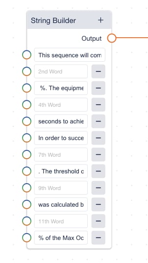
A String Builder block configured for the sequence description with alternating static text and variable inputs from logic blocks
Sensor reading message
This message outputs repeatedly during the sequence each time a new point value is received. It displays the measured value and the required threshold. Template:- Discharge Airflow:
Primary Sensor Input- Threshold 1:
Calculated Threshold 1
Sequence success/failure message
This message outputs at the end of the sequence to confirm the result. Modify the text directly to match your test.- Success: “Damper successfully closed.”
- Failure: “Damper failed to close.”
Initial conditions string builder
The initial conditions section prints the overall workflow description and the starting values of each point per device. Workflow description template: This workflow will test a VAV box for its damper operation. First, we display the initial conditions of the equipment, then we perform pre-condition checks to ensure the equipment is ready to be tested, next we will close the damper and then open the damper measuring airflow to validate the operation. Device initial conditions template:- Device Type:
- Point Name 1 -
Point Value 1- Point Name 2 -
Point Value 2
Pre-conditions check string builder
Pre-condition checks come in two forms, each requiring a success and failure message. State check: Success:Device Type- is
Required State- and passes the pre-condition check.
Device Type- is not
Required State- and fails the pre-condition check.
Device Type- Airflow/Pressure/Temperature does meet the maximum threshold.
- Sensor:
Point Value- . Min/Max Threshold:
Parameter
Device Type- Airflow/Pressure/Temperature does not meet the minimum threshold.
- Sensor:
Point Value- . Min/Max Threshold:
Parameter
Step 4: quality assurance
Use the debugger to validate each section of the workflow. Open theDebugger tab, review and adjust parameter values, then select Start Simulation.
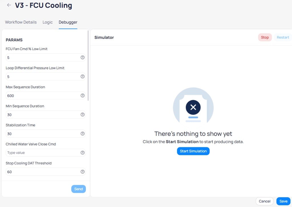
The debugger PARAMS panel where you set parameter values before running a simulation
Initial conditions
For each device type, verify:- The correct device type prints
- The correct point names print
- The correct point values print
Pre-condition checks
For each check, test both the success and failure case. UpdateINPUT values in the debugger to simulate different equipment conditions.
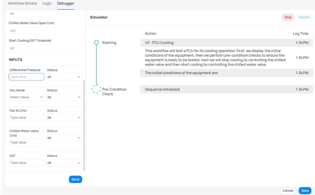
The INPUTS panel during simulation where you send sensor values to test workflow responses
Control sequences
For each sequence, verify:- The threshold calculation is correct
- The sequence passes when the sensor reaches the threshold
- The sequence fails when values approach but do not reach the threshold
- The string builders produce consistent description and sensor reading messages
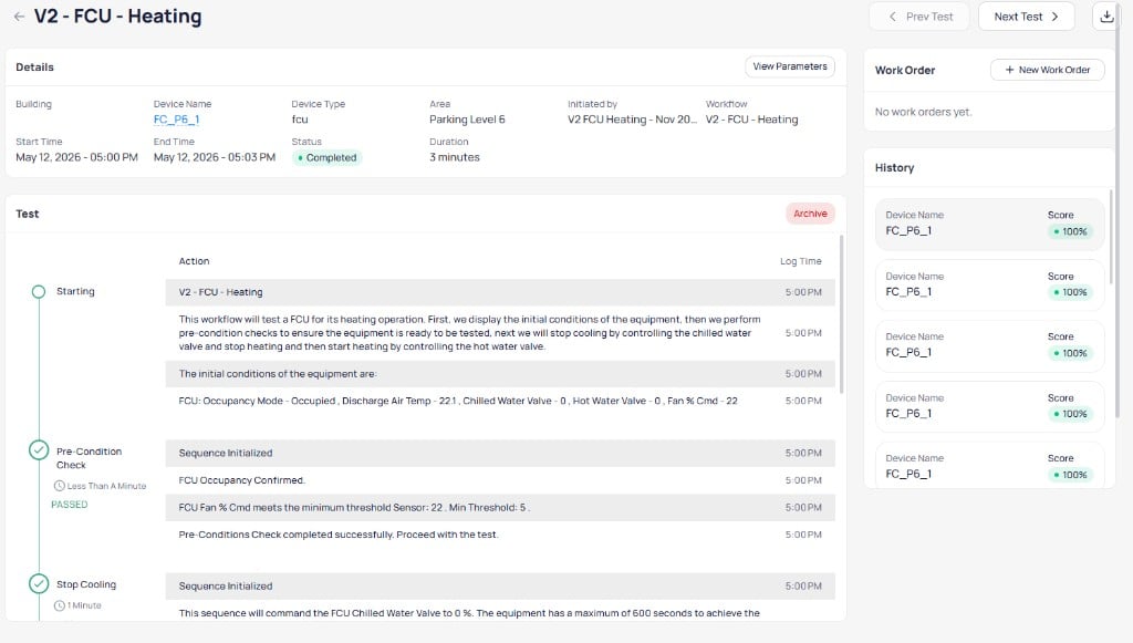
A real test result showing the output format your workflow should produce
Scaling to complex use cases
The standard architecture extends to handle advanced scenarios. These patterns can be combined within a single sequence as needed.Multiple write commands in a single sequence
Issue commands to multiple points within a single sequence, such as commanding both a damper and a fan. Connect both write commands through an AND block before proceeding to the comparison logic.Calculated command values
Derive the command value from sensor data or parameters rather than using a fixed value. Add a Calculation Logic block between the command parameter and the write command.Multiple success criteria
Evaluate two or more conditions that must both pass for the sequence to succeed. Add a second comparison path with its own sensor, threshold, and calculation, then connect both comparisons through an OR block. String builder template for multiple success criteria:- This sequence will command the VAV setpoint to
Calc Value- The equipment has a maximum of
Max Duration- seconds to achieve the success criteria.
- In order to succeed the VAV DAT must be less than
Calculated Threshold 1- or less than
Calculated Threshold 2- . The threshold of
Calculated Threshold 1- assumes that when heating is stopped the VAV discharge air temp will approach the VAV zone temp with a buffer of
Calc Param 1- . The threshold of
Calculated Threshold 2- assumes that when heating is stopped the VAV discharge air temp will approach the AHU discharge air temperature with a buffer of
Calc Param 2
Definitions
Workflow components
Workflow components
Sequence components
Sequence components
String builder messages
String builder messages