> ## Documentation Index
> Fetch the complete documentation index at: https://documentation.kodelabs.com/llms.txt
> Use this file to discover all available pages before exploring further.
# Workflow creator guide
> Build custom FTT workflows when the library does not match your sequence of operations.
This guide is for building **custom** FTT workflows after you understand how library tests score equipment. You design the conceptual test, classify inputs and outputs, build logic in the workflow builder, construct report text, and validate with the debugger.
If you are new to FTT, start with [What is Functional Testing?](/products/ftt/overview) and [What is Functional Testing?](/products/ftt/overview). Most sites deploy library workflows first. Use this guide when a library workflow does not match your sequence of operations.
Before you create a custom workflow, review [Workflow logic blocks](/products/ftt/workflow-logic-blocks) for available block types.
## When to build a custom workflow
Use the library when a standard VAV, FCU, AHU, or heat pump workflow already matches the component you need to score. Build a custom workflow when you need a different command path, sensor set, or success criteria.
Common situations that lead to custom work:
* Continuous commissioning at scale for terminal units across heating and cooling seasons
* Retail or multi-site validation before and after a service visit
* New construction prioritization so agents re-test failed units instead of spot-checking a small sample
## Workflow architecture
Every workflow in the KODE standard architecture contains the following components:
| Component | Description |
| --------------------------- | -------------------------------------------------------------------- |
| **Device type** | Equipment type the workflow tests (VAV, FCU, AHU) |
| **Sensor inputs** | Points that read from the device to indicate operating conditions |
| **Required states** | Conditions that must be met before testing begins |
| **Parameters** | User-adjustable values that control success criteria and time limits |
| **Initial condition logic** | Prints the starting state of the equipment |
| **Pre-condition logic** | Verifies the equipment is in a suitable state for testing |
| **Sequence logic** | Commands equipment and evaluates pass or fail results |
| **Release** | Ends the test and releases all overrides |
```mermaid actions={false} theme={"theme":{"light":"github-dark","dark":"github-dark"}}
---
config:
theme: neutral
layout: dagre
---
flowchart LR
SI["Sensor
Inputs"]:::Lavender
RS["Required
States"]:::Mint
P["Parameters"]:::Lavender
IC["Initial
Conditions"]:::Navy
PC["Pre-condition
Check"]:::Navy
S1["Sequence 1"]:::Lavender
S2["Sequence 2"]:::Lavender
REL["Release"]:::Mint
SI --> IC
IC -.-> PC
RS --> PC
PC --> S1
S1 --> S2
S2 --> REL
P --> S1
P --> S2
linkStyle 0,1,2,3,4,5 stroke:#374D7C
linkStyle 6,7 stroke:#7B68AE
classDef Lavender stroke-width:1px, stroke:#9B8EC4, fill:#E2E0F0, color:#4A3780
classDef Navy stroke-width:1px, stroke:#374D7C, fill:#B8D4E8, color:#374D7C
classDef Mint stroke-width:1px, stroke:#5CA87C, fill:#D0F0DB, color:#2D6B4E
```
### Time control parameters
KODE standard architecture uses three time control parameters in every workflow. These are user-adjustable and applied consistently to each sequence.
| Parameter | Description | Units |
| ----------------------- | ------------------------------------------------------------------------------------------------------------------------- | ------- |
| `Min Sequence Duration` | Minimum duration of each sequence, giving the equipment time to respond to the command | Seconds |
| `Max Sequence Duration` | Maximum duration of each sequence. If the equipment does not reach success criteria within this time, the sequence fails. | Seconds |
| `Stabilization Time` | Buffer time between moving from one sequence to the next | Seconds |
## Sequence architecture
Sequences are the core building blocks of a workflow. Each sequence tests one mechanical component by issuing a command, monitoring the sensor response, and scoring the result. Sequences are isolated to the smallest individual component of the device that you want to test and score.
```mermaid actions={false} theme={"theme":{"light":"github-dark","dark":"github-dark"}}
---
config:
theme: neutral
layout: dagre
---
flowchart LR
T["Trigger"]:::Mint
CV["Cmd Value"]:::Lavender
WC["Write Cmd"]:::Navy
PSI["Primary
Sensor Input"]:::Lavender
BT["Base
Threshold"]:::Lavender
CP["Calc
Parameter"]:::Lavender
CL["Calculation
Logic"]:::Navy
COMP["Comparison"]:::Rose
SO["Sequence
Output"]:::Mint
TC["Time Control"]:::Navy
MSG["String Builder
Messages"]:::Orange
T --> WC
CV --> WC
WC -.-> MSG
PSI --> COMP
BT --> CL
CP --> CL
CL --> COMP
COMP --> SO
COMP -.-> TC
COMP -.-> MSG
linkStyle 0,1,3,4,5,6,7 stroke:#374D7C
linkStyle 2,8,9 stroke:#E67E22
classDef Lavender stroke-width:1px, stroke:#9B8EC4, fill:#E2E0F0, color:#4A3780
classDef Navy stroke-width:1px, stroke:#374D7C, fill:#B8D4E8, color:#374D7C
classDef Mint stroke-width:1px, stroke:#5CA87C, fill:#D0F0DB, color:#2D6B4E
classDef Rose stroke-width:1px, stroke:#FF5978, fill:#FFDFE5, color:#8E2236
classDef Orange stroke-width:1px, stroke:#E67E22, fill:#FDEBD0, color:#935116
```
### Components of a sequence
| Component | Description | Example |
| ------------------------- | ------------------------------------------------------ | ----------------------------------- |
| **Trigger** | Logical input that starts the sequence | Start signal from previous sequence |
| **Write command** | Point override issued to the equipment | VAV Damper Command |
| **Command value** | Specific value written via the command | 0% (close) or 100% (open) |
| **Primary sensor input** | Response variable compared against the threshold | VAV Discharge Airflow |
| **Base threshold** | Reference value for calculating the success criteria | Max Occupied Cooling Flow |
| **Calculation parameter** | User-adjustable modifier applied to the base threshold | 10% |
| **Calculation logic** | Operation between base threshold and parameter | Multiplication |
| **Calculated threshold** | Final value the sensor must reach to pass | 10% of Max Occupied Cooling Flow |
| **Comparison** | How the sensor is compared to the threshold | Less than or equal |
### Sequence string builders
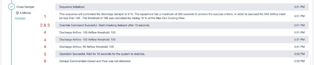
Each sequence generates six messages in the test report:
| Message | Description |
| ---------------------------- | ------------------------------------------------------------------------------------------------- |
| **Sequence description** | What is being commanded, the time limit, the success criteria, and how thresholds were calculated |
| **Command success/failure** | Whether the write command to the equipment succeeded |
| **Minimum duration** | The minimum wait time before evaluating the sequence |
| **Sensor reading** | Real-time sensor value and required threshold (updates repeatedly) |
| **Stabilization** | Buffer time after the sequence passes or fails |
| **Sequence success/failure** | Final pass or fail result for the sequence |
 ## Step 1: conceptual design
Define each sequence, write command, and success criteria before opening the logic builder. This section uses VAV Damper Operation as a working example.
```mermaid actions={false} theme={"theme":{"light":"github-dark","dark":"github-dark"}}
---
config:
theme: neutral
---
flowchart TB
subgraph PC["Pre-condition Check"]
direction TB
P1["VAV Occupancy"]:::Navy
P2["AHU Occupancy"]:::Navy
P3["AHU Pressure"]:::Navy
end
subgraph CD["Close Damper"]
direction TB
C1["Control: damper closed"]:::Lavender
C2["Success if airflow ≤ 10%\nof max occ cooling flow"]:::Lavender
end
subgraph OD["Open Damper"]
direction TB
O1["Control: damper open"]:::Mint
O2["Success if airflow ≥ 90%\nof max occ cooling flow"]:::Mint
end
PC -- "pass" --> CD -- "pass" --> OD
linkStyle 0,1 stroke:#374D7C,stroke-width:2px
style PC fill:#B8D4E8, stroke:#374D7C, color:#374D7C, stroke-width:2px
style CD fill:#E2E0F0, stroke:#9B8EC4, color:#4A3780, stroke-width:2px
style OD fill:#D0F0DB, stroke:#5CA87C, color:#2D6B4E, stroke-width:2px
classDef Navy stroke-width:1px, stroke:#374D7C, fill:#B8D4E8, color:#374D7C
classDef Lavender stroke-width:1px, stroke:#9B8EC4, fill:#E2E0F0, color:#4A3780
classDef Mint fill:#D0F0DB, color:#2D6B4E, stroke:#5CA87C, stroke-width:1px
```
Identify the states the equipment must be in for a valid test. Ask: what conditions ensure the test produces a meaningful mechanical result?
| Sensor value | Requirement | Type |
| --------------- | ---------------------------- | --------------- |
| `VAV Occupancy` | Occupied | State check |
| `AHU Occupancy` | Occupied | State check |
| `AHU Pressure` | `AHU Min Pressure Threshold` | Threshold check |
For each mechanical component to test, specify the write command, sensor input, threshold calculation, and comparison type.
| Component | Value | Type |
| --------------------- | --------------------------- | --------------- |
| Write command | VAV Damper Command | Workflow design |
| Command value | 0% | User input |
| Primary sensor input | VAV Discharge Airflow | Sensor input |
| Base threshold | Max Occupied Cooling Flow | Sensor input |
| Calculation parameter | 10% | User input |
| Calculation logic | Multiplication | Workflow design |
| Calculated threshold | 10% of Max Occ Cooling Flow | Calculated |
| Comparison | Less than or equal | Workflow design |
| Component | Value | Type |
| --------------------- | --------------------------- | --------------- |
| Write command | VAV Damper Command | Workflow design |
| Command value | 100% | User input |
| Primary sensor input | VAV Discharge Airflow | Sensor input |
| Base threshold | Max Occupied Cooling Flow | Sensor input |
| Calculation parameter | 90% | User input |
| Calculation logic | Multiplication | Workflow design |
| Calculated threshold | 90% of Max Occ Cooling Flow | Calculated |
| Comparison | Greater than or equal | Workflow design |
Organize every point and value into four categories. This determines which logic block type to use in the builder.
| Sensor inputs | Required states | Parameters | Write commands |
| ------------------------ | --------------- | -------------------------------- | -------------------- |
| AHU Occupancy | AHU Occupied | Max Sequence Duration | VAV Damper Close Cmd |
| AHU Pressure | VAV Occupied | Min Sequence Duration | VAV Damper Open Cmd |
| VAV Occupancy | | Stabilization Time | |
| VAV Discharge Airflow | | AHU Min Pressure | |
| VAV Max Occ Cooling Flow | | Close Cmd | |
| | | Lower Bound - Airflow Multiplier | |
| | | Open Cmd | |
| | | Upper Bound - Airflow Multiplier | |
## Step 2: build the workflow
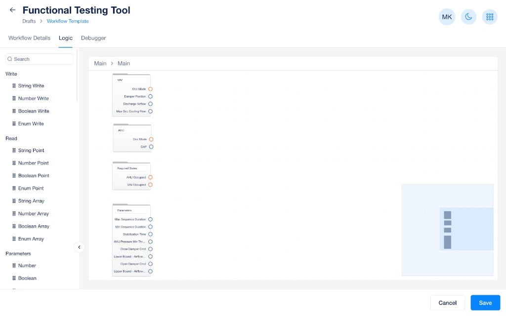
Create the workflow and populate the main folder with sub-folders for device types, required states, and parameters. Add read blocks, parameter blocks, and write commands to their respective folders. The write commands are used later inside specific sequences.
## Step 1: conceptual design
Define each sequence, write command, and success criteria before opening the logic builder. This section uses VAV Damper Operation as a working example.
```mermaid actions={false} theme={"theme":{"light":"github-dark","dark":"github-dark"}}
---
config:
theme: neutral
---
flowchart TB
subgraph PC["Pre-condition Check"]
direction TB
P1["VAV Occupancy"]:::Navy
P2["AHU Occupancy"]:::Navy
P3["AHU Pressure"]:::Navy
end
subgraph CD["Close Damper"]
direction TB
C1["Control: damper closed"]:::Lavender
C2["Success if airflow ≤ 10%\nof max occ cooling flow"]:::Lavender
end
subgraph OD["Open Damper"]
direction TB
O1["Control: damper open"]:::Mint
O2["Success if airflow ≥ 90%\nof max occ cooling flow"]:::Mint
end
PC -- "pass" --> CD -- "pass" --> OD
linkStyle 0,1 stroke:#374D7C,stroke-width:2px
style PC fill:#B8D4E8, stroke:#374D7C, color:#374D7C, stroke-width:2px
style CD fill:#E2E0F0, stroke:#9B8EC4, color:#4A3780, stroke-width:2px
style OD fill:#D0F0DB, stroke:#5CA87C, color:#2D6B4E, stroke-width:2px
classDef Navy stroke-width:1px, stroke:#374D7C, fill:#B8D4E8, color:#374D7C
classDef Lavender stroke-width:1px, stroke:#9B8EC4, fill:#E2E0F0, color:#4A3780
classDef Mint fill:#D0F0DB, color:#2D6B4E, stroke:#5CA87C, stroke-width:1px
```
Identify the states the equipment must be in for a valid test. Ask: what conditions ensure the test produces a meaningful mechanical result?
| Sensor value | Requirement | Type |
| --------------- | ---------------------------- | --------------- |
| `VAV Occupancy` | Occupied | State check |
| `AHU Occupancy` | Occupied | State check |
| `AHU Pressure` | `AHU Min Pressure Threshold` | Threshold check |
For each mechanical component to test, specify the write command, sensor input, threshold calculation, and comparison type.
| Component | Value | Type |
| --------------------- | --------------------------- | --------------- |
| Write command | VAV Damper Command | Workflow design |
| Command value | 0% | User input |
| Primary sensor input | VAV Discharge Airflow | Sensor input |
| Base threshold | Max Occupied Cooling Flow | Sensor input |
| Calculation parameter | 10% | User input |
| Calculation logic | Multiplication | Workflow design |
| Calculated threshold | 10% of Max Occ Cooling Flow | Calculated |
| Comparison | Less than or equal | Workflow design |
| Component | Value | Type |
| --------------------- | --------------------------- | --------------- |
| Write command | VAV Damper Command | Workflow design |
| Command value | 100% | User input |
| Primary sensor input | VAV Discharge Airflow | Sensor input |
| Base threshold | Max Occupied Cooling Flow | Sensor input |
| Calculation parameter | 90% | User input |
| Calculation logic | Multiplication | Workflow design |
| Calculated threshold | 90% of Max Occ Cooling Flow | Calculated |
| Comparison | Greater than or equal | Workflow design |
Organize every point and value into four categories. This determines which logic block type to use in the builder.
| Sensor inputs | Required states | Parameters | Write commands |
| ------------------------ | --------------- | -------------------------------- | -------------------- |
| AHU Occupancy | AHU Occupied | Max Sequence Duration | VAV Damper Close Cmd |
| AHU Pressure | VAV Occupied | Min Sequence Duration | VAV Damper Open Cmd |
| VAV Occupancy | | Stabilization Time | |
| VAV Discharge Airflow | | AHU Min Pressure | |
| VAV Max Occ Cooling Flow | | Close Cmd | |
| | | Lower Bound - Airflow Multiplier | |
| | | Open Cmd | |
| | | Upper Bound - Airflow Multiplier | |
## Step 2: build the workflow
Create the workflow and populate the main folder with sub-folders for device types, required states, and parameters. Add read blocks, parameter blocks, and write commands to their respective folders. The write commands are used later inside specific sequences.
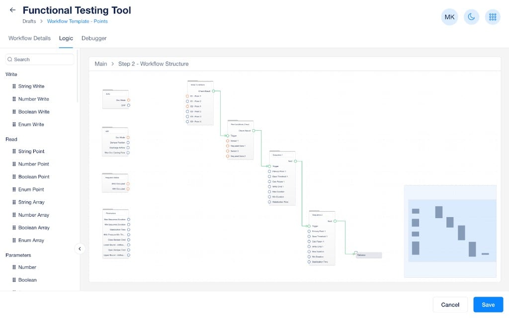
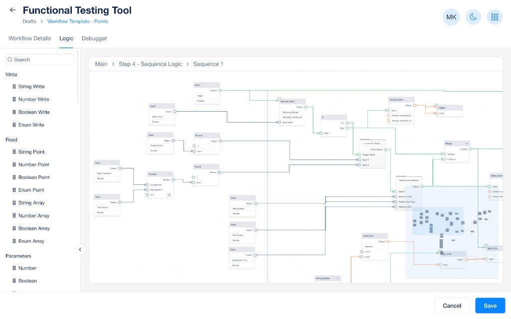
 Create folders for initial conditions, pre-condition checks, and each control sequence. Connect the main inputs and outputs to form the overall workflow structure.
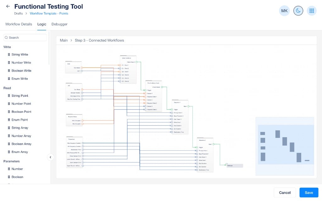
 Connect your sensor inputs, required states, parameters, and write commands into the appropriate folders. This completes the high-level wiring of the workflow.
 Open each sequence folder and configure the logic blocks. For each control sequence, ask:
* Am I writing the correct point field?
* Am I doing the proper calculation on my base threshold (multiplication, addition, subtraction)?
* Am I doing the proper comparison (less than, greater than, equal to)?
Open each sequence folder and configure the logic blocks. For each control sequence, ask:
* Am I writing the correct point field?
* Am I doing the proper calculation on my base threshold (multiplication, addition, subtraction)?
* Am I doing the proper comparison (less than, greater than, equal to)?
 ## Step 3: build text output
Use string builder blocks to combine static text with variable inputs from the logic. The command success/failure, minimum duration, and stabilization messages are standard and generally do not require modification. Focus on customizing the three messages below.
In the templates below, *italic text* represents static text you should customize for your test. `Backtick text` represents dynamic values populated by drawing lines from logic blocks into the string builder.
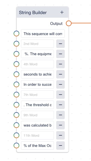
### Sequence description message
This message describes the command being issued, the maximum time duration, the success criteria, and how the thresholds were calculated.
Template:
1. This sequence will command the *VAV Damper Cmd* to
2. `Command Value`
3. %. The equipment has a maximum of
4. `Max Duration`
5. seconds to achieve the success criteria.
6. In order to succeed the
7. *VAV Airflow must be less than*
8. `Calculated Threshold`
9. . The threshold of
10. `Calculated Threshold`
11. was calculated by taking:
12. `Parameter Calc`
13. *% of the Max Occ Cooling Flow.*
## Step 3: build text output
Use string builder blocks to combine static text with variable inputs from the logic. The command success/failure, minimum duration, and stabilization messages are standard and generally do not require modification. Focus on customizing the three messages below.
In the templates below, *italic text* represents static text you should customize for your test. `Backtick text` represents dynamic values populated by drawing lines from logic blocks into the string builder.
### Sequence description message
This message describes the command being issued, the maximum time duration, the success criteria, and how the thresholds were calculated.
Template:
1. This sequence will command the *VAV Damper Cmd* to
2. `Command Value`
3. %. The equipment has a maximum of
4. `Max Duration`
5. seconds to achieve the success criteria.
6. In order to succeed the
7. *VAV Airflow must be less than*
8. `Calculated Threshold`
9. . The threshold of
10. `Calculated Threshold`
11. was calculated by taking:
12. `Parameter Calc`
13. *% of the Max Occ Cooling Flow.*
 ### Sensor reading message
This message outputs repeatedly during the sequence each time a new point value is received. It displays the measured value and the required threshold.
Template:
1. *Discharge Airflow*:
2. `Primary Sensor Input`
3. *Threshold 1*:
4. `Calculated Threshold 1`
### Sequence success/failure message
This message outputs at the end of the sequence to confirm the result. Modify the text directly to match your test.
* Success: *"Damper successfully closed."*
* Failure: *"Damper failed to close."*
### Initial conditions string builder
The initial conditions section prints the overall workflow description and the starting values of each point per device.
**Workflow description template:**
This workflow will test a *VAV box* for its *damper operation*. First, we display the initial conditions of the equipment, then we perform pre-condition checks to ensure the equipment is ready to be tested, next we will *close the damper* and then *open the damper* measuring *airflow* to validate the operation.
**Device initial conditions template:**
1. *Device Type*:
2. *Point Name 1* -
3. `Point Value 1`
4. *Point Name 2* -
5. `Point Value 2`
### Pre-conditions check string builder
Pre-condition checks come in two forms, each requiring a success and failure message.
**State check:**
Success:
1. `Device Type`
2. *is*
3. `Required State`
4. *and passes the pre-condition check.*
Failure:
1. `Device Type`
2. *is not*
3. `Required State`
4. *and fails the pre-condition check.*
**Threshold check:**
Success:
1. `Device Type`
2. *Airflow/Pressure/Temperature does meet the maximum threshold.*
3. *Sensor:*
4. `Point Value`
5. *. Min/Max Threshold:*
6. `Parameter`
Failure:
1. `Device Type`
2. *Airflow/Pressure/Temperature does not meet the minimum threshold.*
3. *Sensor:*
4. `Point Value`
5. *. Min/Max Threshold:*
6. `Parameter`
## Step 4: quality assurance
Use the debugger to validate each section of the workflow. Open the `Debugger` tab, review and adjust parameter values, then select `Start Simulation`.
### Sensor reading message
This message outputs repeatedly during the sequence each time a new point value is received. It displays the measured value and the required threshold.
Template:
1. *Discharge Airflow*:
2. `Primary Sensor Input`
3. *Threshold 1*:
4. `Calculated Threshold 1`
### Sequence success/failure message
This message outputs at the end of the sequence to confirm the result. Modify the text directly to match your test.
* Success: *"Damper successfully closed."*
* Failure: *"Damper failed to close."*
### Initial conditions string builder
The initial conditions section prints the overall workflow description and the starting values of each point per device.
**Workflow description template:**
This workflow will test a *VAV box* for its *damper operation*. First, we display the initial conditions of the equipment, then we perform pre-condition checks to ensure the equipment is ready to be tested, next we will *close the damper* and then *open the damper* measuring *airflow* to validate the operation.
**Device initial conditions template:**
1. *Device Type*:
2. *Point Name 1* -
3. `Point Value 1`
4. *Point Name 2* -
5. `Point Value 2`
### Pre-conditions check string builder
Pre-condition checks come in two forms, each requiring a success and failure message.
**State check:**
Success:
1. `Device Type`
2. *is*
3. `Required State`
4. *and passes the pre-condition check.*
Failure:
1. `Device Type`
2. *is not*
3. `Required State`
4. *and fails the pre-condition check.*
**Threshold check:**
Success:
1. `Device Type`
2. *Airflow/Pressure/Temperature does meet the maximum threshold.*
3. *Sensor:*
4. `Point Value`
5. *. Min/Max Threshold:*
6. `Parameter`
Failure:
1. `Device Type`
2. *Airflow/Pressure/Temperature does not meet the minimum threshold.*
3. *Sensor:*
4. `Point Value`
5. *. Min/Max Threshold:*
6. `Parameter`
## Step 4: quality assurance
Use the debugger to validate each section of the workflow. Open the `Debugger` tab, review and adjust parameter values, then select `Start Simulation`.
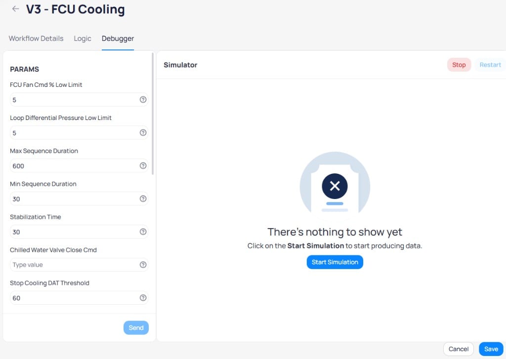 ### Initial conditions
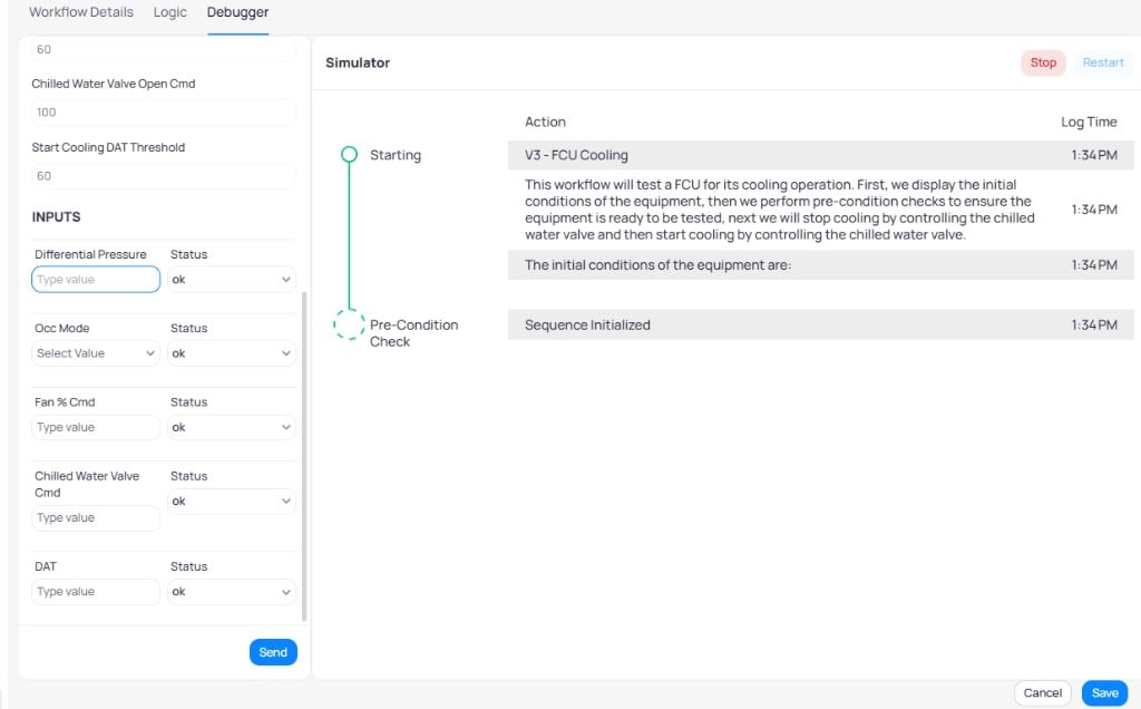
For each device type, verify:
1. The correct device type prints
2. The correct point names print
3. The correct point values print
### Pre-condition checks
For each check, test both the success and failure case. Update `INPUT` values in the debugger to simulate different equipment conditions.
### Initial conditions
For each device type, verify:
1. The correct device type prints
2. The correct point names print
3. The correct point values print
### Pre-condition checks
For each check, test both the success and failure case. Update `INPUT` values in the debugger to simulate different equipment conditions.
 Using the VAV Damper Operation example with three pre-condition checks:
| Pre-condition | Test success | Test failure |
| -------------------------------- | ------------------------------------------------------------------------------------ | ------------------------------------------------------------------------------------ |
| **VAV Occupancy** | Input an occupied value and verify the correct success statement prints | Input an unoccupied value and verify the correct failure statement prints |
| **AHU Occupancy** | Input an occupied value and verify the correct success statement prints | Input an unoccupied value and verify the correct failure statement prints |
| **AHU Pressure above Threshold** | Input a pressure above the threshold and verify the correct success statement prints | Input a pressure below the threshold and verify the correct failure statement prints |
### Control sequences
For each sequence, verify:
1. The threshold calculation is correct
2. The sequence passes when the sensor reaches the threshold
3. The sequence fails when values approach but do not reach the threshold
4. The string builders produce consistent description and sensor reading messages
Compare the debugger output with what a real test result looks like. The sequence names, descriptions, and pass/fail messages should match.
Using the VAV Damper Operation example with three pre-condition checks:
| Pre-condition | Test success | Test failure |
| -------------------------------- | ------------------------------------------------------------------------------------ | ------------------------------------------------------------------------------------ |
| **VAV Occupancy** | Input an occupied value and verify the correct success statement prints | Input an unoccupied value and verify the correct failure statement prints |
| **AHU Occupancy** | Input an occupied value and verify the correct success statement prints | Input an unoccupied value and verify the correct failure statement prints |
| **AHU Pressure above Threshold** | Input a pressure above the threshold and verify the correct success statement prints | Input a pressure below the threshold and verify the correct failure statement prints |
### Control sequences
For each sequence, verify:
1. The threshold calculation is correct
2. The sequence passes when the sensor reaches the threshold
3. The sequence fails when values approach but do not reach the threshold
4. The string builders produce consistent description and sensor reading messages
Compare the debugger output with what a real test result looks like. The sequence names, descriptions, and pass/fail messages should match.
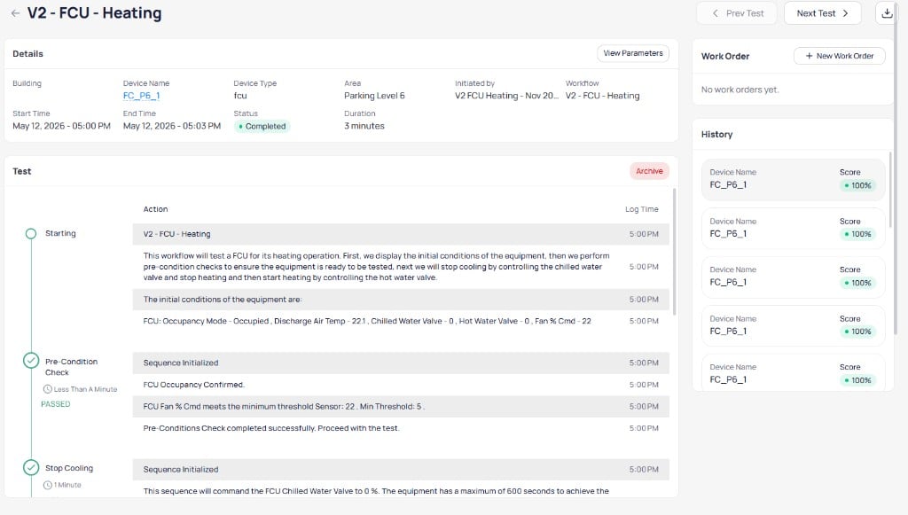 Delay times run in real time during simulation. Temporarily change time units to seconds on timer blocks to speed up testing. Return to the correct units before deploying.
## Scaling to complex use cases
The standard architecture extends to handle advanced scenarios. These patterns can be combined within a single sequence as needed.
### Multiple write commands in a single sequence
Issue commands to multiple points within a single sequence, such as commanding both a damper and a fan. Connect both write commands through an AND block before proceeding to the comparison logic.
```mermaid actions={false} theme={"theme":{"light":"github-dark","dark":"github-dark"}}
---
config:
theme: neutral
layout: dagre
---
flowchart LR
T["Trigger"]:::Mint
WC1["Write Cmd 1"]:::Navy
WC2["Write Cmd 2"]:::Navy
AND["AND"]:::Mint
S1["Sensor 1"]:::Lavender
BT["Base Threshold 1"]:::Lavender
CP["Calc Parameter 1"]:::Lavender
CL["Calculation
Delay times run in real time during simulation. Temporarily change time units to seconds on timer blocks to speed up testing. Return to the correct units before deploying.
## Scaling to complex use cases
The standard architecture extends to handle advanced scenarios. These patterns can be combined within a single sequence as needed.
### Multiple write commands in a single sequence
Issue commands to multiple points within a single sequence, such as commanding both a damper and a fan. Connect both write commands through an AND block before proceeding to the comparison logic.
```mermaid actions={false} theme={"theme":{"light":"github-dark","dark":"github-dark"}}
---
config:
theme: neutral
layout: dagre
---
flowchart LR
T["Trigger"]:::Mint
WC1["Write Cmd 1"]:::Navy
WC2["Write Cmd 2"]:::Navy
AND["AND"]:::Mint
S1["Sensor 1"]:::Lavender
BT["Base Threshold 1"]:::Lavender
CP["Calc Parameter 1"]:::Lavender
CL["Calculation
Logic"]:::Navy
COMP["Comparison"]:::Rose
SO["Sequence
Output"]:::Mint
TC["Time Control"]:::Navy
T -.-> WC1
T -.-> WC2
WC1 --> AND
WC2 --> AND
S1 --> COMP
BT --> CL
CP --> CL
CL --> COMP
AND --> COMP
COMP --> SO
COMP -.-> TC
linkStyle 0,1,2,3,4,5,6,7,8,9 stroke:#374D7C
linkStyle 10 stroke:#374D7C
classDef Lavender stroke-width:1px, stroke:#9B8EC4, fill:#E2E0F0, color:#4A3780
classDef Navy stroke-width:1px, stroke:#374D7C, fill:#B8D4E8, color:#374D7C
classDef Mint stroke-width:1px, stroke:#5CA87C, fill:#D0F0DB, color:#2D6B4E
classDef Rose stroke-width:1px, stroke:#FF5978, fill:#FFDFE5, color:#8E2236
```
### Calculated command values
Derive the command value from sensor data or parameters rather than using a fixed value. Add a Calculation Logic block between the command parameter and the write command.
```mermaid actions={false} theme={"theme":{"light":"github-dark","dark":"github-dark"}}
---
config:
theme: neutral
layout: dagre
---
flowchart LR
T["Trigger"]:::Mint
BCV["Base Cmd
Value"]:::Lavender
CCP["Cmd Calc
Param 1"]:::Rose
CL1["Calculation
Logic"]:::Navy
WC["Write Cmd 1"]:::Navy
S1["Sensor 1"]:::Lavender
BT["Base
Threshold 1"]:::Lavender
CP["Calc
Parameter 1"]:::Lavender
CL2["Calculation
Logic"]:::Navy
COMP["Comparison"]:::Rose
SO["Sequence
Output"]:::Mint
TC["Time Control"]:::Navy
T -.-> WC
BCV --> CL1
CCP --> CL1
CL1 --> WC
S1 --> COMP
BT --> CL2
CP --> CL2
CL2 --> COMP
COMP --> SO
COMP -.-> TC
linkStyle 0,1,2,3,4,5,6,7,8 stroke:#374D7C
linkStyle 9 stroke:#374D7C
classDef Lavender stroke-width:1px, stroke:#9B8EC4, fill:#E2E0F0, color:#4A3780
classDef Navy stroke-width:1px, stroke:#374D7C, fill:#B8D4E8, color:#374D7C
classDef Mint stroke-width:1px, stroke:#5CA87C, fill:#D0F0DB, color:#2D6B4E
classDef Rose stroke-width:1px, stroke:#FF5978, fill:#FFDFE5, color:#8E2236
```
### Multiple success criteria
Evaluate two or more conditions that must both pass for the sequence to succeed. Add a second comparison path with its own sensor, threshold, and calculation, then connect both comparisons through an OR block.
```mermaid actions={false} theme={"theme":{"light":"github-dark","dark":"github-dark"}}
---
config:
theme: neutral
layout: dagre
---
flowchart LR
T["Trigger"]:::Mint
CV["Cmd Value"]:::Lavender
WC["Write Cmd"]:::Navy
subgraph path1["Criteria 1"]
S1["Sensor 1"]:::Lavender
BT1["Base Threshold 1"]:::Lavender
CP1["Calc Param 1"]:::Lavender
CL1["Calc Logic"]:::Navy
COMP1["Comparison"]:::Rose
end
subgraph path2["Criteria 2"]
S1b["Sensor 1"]:::Lavender
BT2["Base Threshold 2"]:::Orange
CP2["Calc Param 2"]:::Orange
CL2["Calc Logic"]:::Navy
COMP2["Comparison"]:::Navy
end
OR["OR"]:::Mint
SO["Sequence
Output"]:::Mint
TC["Time Control"]:::Navy
T --> WC
CV --> WC
S1 --> COMP1
BT1 --> CL1
CP1 --> CL1
CL1 --> COMP1
S1b --> COMP2
BT2 --> CL2
CP2 --> CL2
CL2 --> COMP2
COMP1 --> OR
COMP2 --> OR
OR --> SO
OR -.-> TC
linkStyle 0,1,2,3,4,5,6,7,8,9,10,11,12 stroke:#374D7C
linkStyle 13 stroke:#374D7C
classDef Lavender stroke-width:1px, stroke:#9B8EC4, fill:#E2E0F0, color:#4A3780
classDef Navy stroke-width:1px, stroke:#374D7C, fill:#B8D4E8, color:#374D7C
classDef Mint stroke-width:1px, stroke:#5CA87C, fill:#D0F0DB, color:#2D6B4E
classDef Rose stroke-width:1px, stroke:#FF5978, fill:#FFDFE5, color:#8E2236
classDef Orange stroke-width:1px, stroke:#E67E22, fill:#FDEBD0, color:#935116
style path1 fill:none, stroke:#9B8EC4, stroke-dasharray:5
style path2 fill:none, stroke:#E67E22, stroke-dasharray:5
```
**String builder template for multiple success criteria:**
1. This sequence will command the *VAV setpoint* to
2. `Calc Value`
3. The equipment has a maximum of
4. `Max Duration`
5. seconds to achieve the success criteria.
6. *In order to succeed the VAV DAT must be less than*
7. `Calculated Threshold 1`
8. *or less than*
9. `Calculated Threshold 2`
10. . The threshold of
11. `Calculated Threshold 1`
12. *assumes that when heating is stopped the VAV discharge air temp will approach the VAV zone temp with a buffer of*
13. `Calc Param 1`
14. . The threshold of
15. `Calculated Threshold 2`
16. *assumes that when heating is stopped the VAV discharge air temp will approach the AHU discharge air temperature with a buffer of*
17. `Calc Param 2`
Start with the standard architecture and expand as needed. The logic for multiple write commands, calculated values, and multiple criteria can be combined within a single sequence.
## Definitions
| Term | Definition | Examples |
| --------------------------- | --------------------------------------------------------------------------------------------------------- | -------------------------------------------------------- |
| **Device type** | The type of equipment the workflow is compatible with | VAV, FCU, AHU |
| **Sensor inputs** | Points that read from a device to indicate operating conditions | Zone Temp, Discharge Air Temp, Discharge Airflow |
| **Required states** | Constant values required to ensure the equipment is in a suitable state | AHU Occupied Mode, Boiler Run Status, VAV Heating Mode |
| **Parameters** | User-adjustable preferences that specify requirements such as thresholds, time limits, and command values | Airflow low limit, Max Duration, Damper Command |
| **Initial condition logic** | Prints the starting state of equipment at test start | Initial zone temperature, airflow, damper position |
| **Pre-condition logic** | Checks initial conditions to ensure the test produces a valid mechanical result | Verify hot water loop run status before testing heating |
| **Sequence logic** | Commands equipment and checks success criteria to produce pass/fail scores | Close Damper sequence commands damper and checks airflow |
| **Release** | Ends the test and releases all overrides | Required in every workflow |
| Term | Definition | Examples |
| ------------------------- | ------------------------------------------------------------------------------ | -------------------------------------------------------- |
| **Trigger** | Logical input that starts a process | Starts a sequence, writes a command, or outputs a string |
| **Write command** | Issues a command to a device point. Outputs true on success, false on failure. | VAV Damper Command to 0%, Fan Commanded On |
| **Command value** | Fixed value or user input determining the value written via a command | 0%, 100%, ON |
| **Primary sensor input** | Response variable compared directly to the calculated threshold | VAV Discharge Temperature, VAV Airflow |
| **Base threshold** | Key value from which the final requirement is calculated | Max Occ Cooling Flow, AHU DAT |
| **Calculation parameter** | User-adjustable parameter that modifies the difficulty of the test | % of Max Occ Cooling Flow, AHU Temp Differential |
| **Calculation logic** | Operation between the base threshold and calculation parameter | 90% \* Max Occ Cooling Flow, AHU DAT + Temp Differential |
| **Calculated threshold** | Final value the sensor must reach to pass or fail | Airflow Threshold = 90% of Max Occ Cooling Flow |
| **Comparison** | Comparison between the sensor and threshold(s) | Less than or equal, greater than or equal, equals |
| Term | Definition | Example |
| ------------------------- | ------------------------------------------------------------------------------- | ------------------------------------------------------------------------------------------------------ |
| **Sequence description** | Describes the command, time limit, success criteria, and threshold calculations | "This sequence will command the discharge damper to 0%. The equipment has a maximum of 300 seconds..." |
| **Command failure** | Informs if the command to equipment succeeded | "Override not Successful." |
| **Minimum duration** | Informs of the minimum wait time before evaluating | "Override Command Successful. Start checking feedback after 30 seconds." |
| **Sensor reading** | Displays measured value and required threshold repeatedly | "Discharge Airflow: 200 Airflow threshold: 100" |
| **Stabilization** | Buffer time period after success/failure before the next sequence | "Operation Successful. Wait for 30 seconds for the system to stabilize" |
| **Sequence success/fail** | Confirms if the sequence succeeded or failed | "Damper successfully opened." |
## Next steps
Reference guide for all available block types.
Manage and test workflows in the logic builder.
Assign workflows to devices and schedule testing.
Roll out library workflows before you invest in custom logic.